Snow and wind load calculation BS EN 1991 for solar carport and PV structures in the UK
Method to determine your ground snow load and basic wind velocity under BS EN 1991-1-3/1-4 and the UK National Annexes, with the UK formulas and worked examples for London, Manchester and Edinburgh.

Quick answer. In the UK, the snow and wind loads on a solar carport, canopy or PV mounting structure come from BS EN 1991-1-3 (snow) and BS EN 1991-1-4 (wind) with their UK National Annexes. The characteristic ground snow load is sk = [0.15 + (0.1Z + 0.05)] + (A − 100)/525 kN/m², where Z is the snow zone read from the National Annex map and A the site altitude in metres: it rises by about 0.19 kN/m² per 100 m of altitude. The basic wind velocity map value vb,map runs from about 21.5 m/s in South-East England to around 30 m/s in the far north of Scotland, before the altitude correction. The roof snow load is s = μi × Ce × Ct × sk; wind becomes a peak velocity pressure qp(z), multiplied by pressure coefficients that are highest at edges and corners. Postcode and site altitude give the starting values; a site-specific calculation turns them into section sizes, post spacing and anchorages.
Scope of this guide. Examples explain the workflow; they are not design values for your site. A calculation must identify the applicable standards and National Annexes, site data and checked assumptions. A study does not replace planning permission or the terms of your insurance.
Snow, wind and anchorage must be assessed together when designing a photovoltaic support structure. The design basis should identify the applicable BS EN standards, UK National Annexes and project requirements. Compliance, permissions and insurance cover must be checked for the particular project, not inferred from a generic product claim.
This article explains, without unnecessary jargon, how to identify your snow zone, calculate the characteristic ground snow load sk, read the basic wind velocity vb,map, and why exposed sites need particular care. You will find the 3-step method, three worked examples (London, Manchester, Edinburgh), and the common pitfalls of “cheap solar carport” kits that advertise a generic “snow resistance” without any calculation evidence.
Why site-specific snow and wind checks matter
Three structural considerations deserve particular attention:
- Light structure, large surface. A solar carport is a light frame carrying a large area of modules. Its own weight is small compared with the climatic loads (snow, wind) acting on that area, so those loads govern the design.
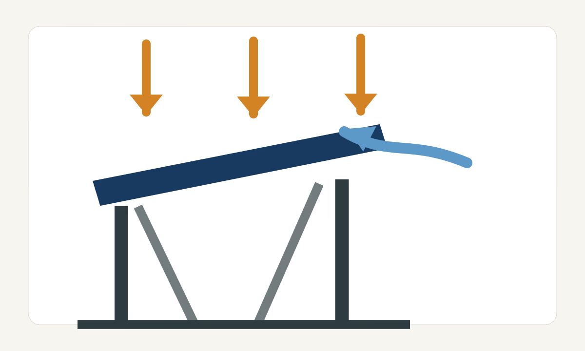
- Wind uplift on canopies. An open canopy is loaded from above and below. Uplift is often what governs the connections and the anchorages, especially at edges and corners.
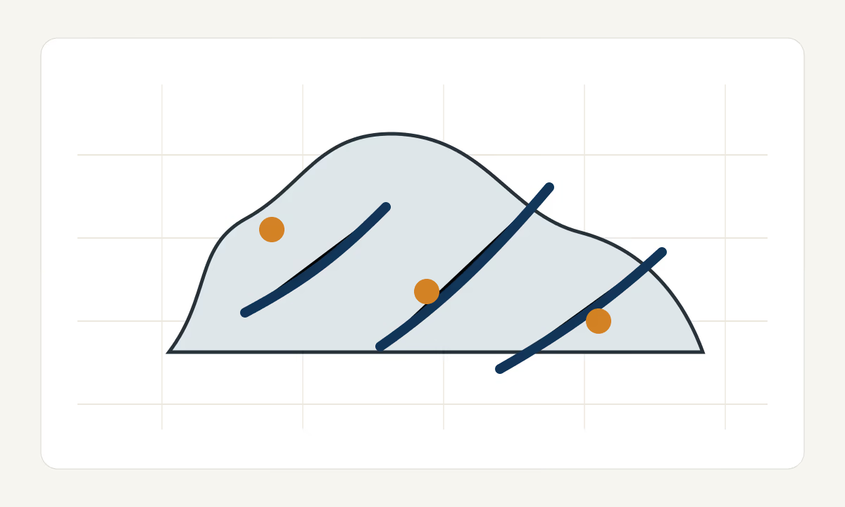
- Snow does not accumulate uniformly. BS EN 1991-1-3 gives shape coefficients depending on roof geometry, and the UK National Annex requires its Annex B to be used for drifting against obstructions and abutting taller structures. A carport built against a house wall is a typical case.
At Sunrak, the structural study is ordered and paid for before the hardware quotation, and its fee may be fully credited against the structure under the stated conditions. It replaces a generic “snow rating” with checks against your site’s actual loads.
Snow loads under BS EN 1991-1-3 in the UK
The UK National Annex (NA to BS EN 1991-1-3) divides the UK into snow zones shown on a map (Figure NA.1). Each zone has a ground snow load at 100 m above sea level, and the altitude of the site is then added through a formula.
Ground snow load by zone (at 100 m altitude)
Zone Z (Figure NA.1) | sk at 100 m above sea level |
|---|---|
| 1 | 0.30 kN/m² |
| 2 | 0.40 kN/m² |
| 3 | 0.50 kN/m² |
| 4 | 0.60 kN/m² |
| 5 | 0.70 kN/m² |
| 6.5 (very limited areas) | 0.85 kN/m² |
Zones 4 and 5 cover much of upland northern England and Scotland; large parts of lowland England are in zones 2 and 3. Always read the zone for the exact site on the map.
Altitude correction
The UK National Annex formula (Equation NA.1, as corrected in 2007) is:
sk = [0.15 + (0.1Z + 0.05)] + (A − 100)/525 (kN/m²)with Z the zone number and A the site altitude in metres. Below 100 m the altitude term is negative; above 100 m, sk increases by about 0.19 kN/m² for each additional 100 m. The National Annex warns that unusual local effects (shelter, funnelling in mountainous areas) may not be captured: where such conditions are suspected, coastal sites below 100 m should use the map value without the altitude reduction, or the Met Office should be consulted.
Roof snow load
The roof load is then computed:
s = μi × Ce × Ct × skwith:
μi— shape coefficient: for a monopitch roof 0.8 for pitch up to 30°, decreasing linearly to zero at 60°; for duo-pitched roofs and drifts, the UK National Annex gives its own arrangementsCe— exposure coefficient: 1.0 in the UK for all topographies (UK National Annex)Ct— thermal coefficient: 1.0 in the UK for all roofing materials (UK National Annex)
Exceptional snow drifts (Annex B) are treated in the UK as accidental design situations.
BSI describes a transition between first- and second-generation Eurocodes. Its BS EN 1991-1-3:2025 notice states that UK adoptions of the first-generation documents will be withdrawn on 30 March 2028 and remain the applicable basis until then unless the authority or project specification says otherwise. Do not mix editions or coefficients without checking their compatibility. BSI transition notice.
Wind loads under BS EN 1991-1-4 in the UK
The UK National Annex to BS EN 1991-1-4 gives a map (Figure NA.1) of the fundamental basic wind velocity vb,map: a 10-minute mean wind speed at 10 m above ground in open country, with an annual probability of exceedance of 0.02 (50-year return period), before altitude correction.
vb,map across the UK
The map values range from about 21.5 m/s in South-East England to around 30 m/s and above in the far north and west of Scotland and the Northern Isles. For example, a published calculation for a London site uses vb,map = 21.4 m/s. Always read the value for the exact site from the map (or compute it from the National Grid coordinates).
From basic velocity to peak velocity pressure
vb,0 = vb,map × calt          calt = 1 + 0.001 × A   (for z ≤ 10 m)
vb   = cdir × cseason × vb,0
qb   = 0.613 × vb²            (N/m², air density 1.226 kg/m³)
qp(z) = ce(z) × qbAis the site altitude in metres (for sites on hills or escarpments, the altitude of the upwind base of the feature);cdirandcseasonmay conservatively be taken as 1.0;ce(z)is the exposure factor from the UK National Annex charts, depending on height above ground, distance to the shoreline and, in town terrain, distance inside town; orography (hills, ridges, escarpments) adds a further factor where significant.
Sensitivity of the basic velocity pressure qb to vb (with cdir = cseason = 1.0):
vb | qb |
|---|---|
| 22 m/s | 0.30 kN/m² |
| 24 m/s | 0.35 kN/m² |
| 26 m/s | 0.41 kN/m² |
| 28 m/s | 0.48 kN/m² |
| 30 m/s | 0.55 kN/m² |
The velocity pressure grows with the square of the speed: +36% of speed between 22 and 30 m/s gives +86% of pressure.
For canopies, BS EN 1991-1-4 section 7.3 gives net pressure coefficients cp,net and force coefficients cf that depend on the roof pitch, the zone (overall, edges, corners) and the blockage under the canopy (parked vehicles, stored goods, a wall at the back). Edge and corner zones carry markedly higher local values than the overall coefficient.
3-step method to identify your loads
Step 1 — Postcode and altitude
The postcode identifies the locality. Ordnance Survey maps give the site altitude. Our study brief asks for the postcode for this reason.
Step 2 — Read snow + wind values
From location + altitude we read:
- the snow zone
Zand the resultingsk(formula above) - the
vb,mapbasic wind velocity and its altitude correction
Step 3 — Action combinations to BS EN 1990
We apply the load combinations of BS EN 1990 with its UK National Annex, for example:
- Persistent ULS, snow leading:
1.35·Gk + 1.5·Qk,s + 0.75·Qk,w(ψ0 = 0.5 for wind in the UK) — and the permutations with wind leading - Uplift:
1.0·Gk + 1.5·Qk,w, with the self-weight acting favourably - Accidental: exceptional snow drift, where Annex B applies
- SLS for deflection, with limits agreed for the project (BS EN 1990 does not fix a universal limit for canopies)
This is what determines the section sizes, the post spacing and the foundation or anchorage principle.
Three worked examples
Snow zones read by us from Figure NA.1 of the UK National Annex; altitudes are illustrative. Roof load for a monopitch carport below 30° (μ1 = 0.8, Ce = Ct = 1.0), on 30 m² of horizontal projection, without drift.
Site 1 — London (W1 area)
| Parameter | Value |
|---|---|
| Altitude (assumed) | 25 m |
| Snow zone | 3 |
sk | 0.15 + 0.35 + (25 − 100)/525 ≈ 0.36 kN/m² |
Roof snow load s | 0.8 × 0.36 ≈ 0.29 kN/m² |
| Total snow on 30 m² | ≈ 8.6 kN |
vb,map | 21.4 m/s (published London calculation) |
vb,0 | 21.4 × 1.025 ≈ 21.9 m/s |
qb | ≈ 0.29–0.30 kN/m² |
Site 2 — Manchester (M1 area)
| Parameter | Value |
|---|---|
| Altitude (assumed) | 38 m |
| Snow zone | 3 |
sk | 0.50 + (38 − 100)/525 ≈ 0.38 kN/m² |
Roof snow load s | ≈ 0.31 kN/m² |
| Total snow on 30 m² | ≈ 9.2 kN |
vb,map | read from Figure NA.1 for the exact site; then qb from the table above |
Site 3 — Edinburgh (EH1 area)
| Parameter | Value |
|---|---|
| Altitude (assumed) | 47 m |
| Snow zone | 3 |
sk | 0.50 + (47 − 100)/525 ≈ 0.40 kN/m² |
Roof snow load s | ≈ 0.32 kN/m² |
| Total snow on 30 m² | ≈ 9.6 kN |
vb,map | read from Figure NA.1 for the exact site; then qb from the table above |
These illustrative cases show why site data matters: altitude, drift against a nearby wall and wind exposure can change the result far more than the city name. A generic kit must be checked against the actual design loads and anchorage requirements before it is specified.
Common pitfalls
Pitfall 1 — Generic “snow resistance” claims. Many kits advertise “supports 60 kg/m² snow load” with no mention of the combination, pitch or drift. This is marketing copy, not a calculation.
Pitfall 2 — Underestimating altitude. In zone 3,
skis about 0.31 kN/m² at sea level but about 1.26 kN/m² at 500 m. A carport checked for a lowland town is not automatically suitable for a hill farm.
Pitfall 3 — Ignoring drift against walls. A carport roof abutting a house or a taller building collects drifted snow; the UK National Annex requires BS EN 1991-1-3 Annex B for these cases.
Pitfall 4 — Wind at edges and corners ignored. Canopy coefficients are higher at edges and corners, and blockage under the canopy changes them. Corner anchorages often govern under storm loading.
Pitfall 5 — Ignoring topography. Hills, ridges and escarpments add an orography factor (
c0 > 1.0) on top of the map velocity; many Scottish and upland sites are concerned.
Pitfall 6 — Foundations forgotten. A well-sized structure on an undersized pad is equally useless. The paid structural study includes the foundation or anchorage principle based on the ground data you supply.
What the Sunrak structural study includes
Sunrak supplies the metal structure only (anodised aluminium 6063-T5 or galvanised steel Z275, stainless fasteners), ready to assemble. The paid structural study, ordered before the hardware quotation, includes:
- Applicable assumptions and wind/snow checks for your site
- Dimensioned general arrangement drawing and layout plan
- Foundation or anchorage principle based on the data you provide
- Bill of materials and assembly instructions
- One round of corrections within the initial scope
It is not an independent certification: if building control, an insurer or a lender asks for third-party verification, that is arranged separately. The study is paid before work begins and the delivered documents remain usable by the customer even if the structure is not ordered from Sunrak. If the structure is ordered within 90 days for the same site and scope, and the equipment order (excluding VAT) is at least five times the study price, the study fee is credited in full against the equipment.
Budgeting the hardware as well? See solar carport prices and the comparison solar carport wood or metal.
FAQ — BS EN 1991 for solar mounting structures
Does BS EN 1991 apply to small carports under 30 m²?
In England and Wales, a carport open on at least two sides with a floor area not exceeding 30 m² is generally exempt from Building Regulations approval (the electrical work for solar PV is still controlled). The loads of BS EN 1991 still exist, though: designing to them is the way to make sure the structure survives snow and storms, and your insurer may ask how it was designed after a claim.
Is CE or UKCA marking on the profiles enough?
No. CE or UKCA marking concerns the construction product itself. It does not replace a project-specific check against your site's snow and wind loads. A profile can be marked and still be under-sized for your site.
What is the difference between BS EN 1991 and the old BS 6399?
BS 6399 was the UK's pre-Eurocode loading standard; BSI withdrew it in 2010 when the Eurocodes took over. New PV mounting designs should use BS EN 1991 with the UK National Annexes.
My site is at 400 m altitude — how does sk change?
With the UK formula, `sk` at 400 m is the zone value at 100 m plus 300/525 ≈ 0.57 kN/m²: about 0.87 kN/m² in zone 1, 1.07 in zone 3 and 1.27 in zone 5 — roughly double or triple the values of a lowland site in the same zone.
Do I need wind calculation for a ground-mount array?
Yes — and this is where wind matters most. A ground-mount is fully exposed, and its anchorage (driven piles, screws or ballast) must resist uplift and sliding. An unverified anchorage can fail in a severe storm.
Does Sunrak include the structural calculation in the quote?
The structural study is a paid step before the equipment quotation. It covers the applicable wind and snow assumptions and checks, a dimensioned general arrangement and layout drawing, the foundation or anchorage principle, the bill of materials and assembly instructions. Its fee is credited against a qualifying structure order under the stated conditions.
How long does the calculation take after my enquiry?
The study is ordered and paid for before the hardware quotation. The schedule is confirmed after the complete brief is checked and any missing information has been clarified.
Is this also useful for the Republic of Ireland?
The method is the same, but Ireland uses its own National Annexes (I.S. EN 1991-1-3 and I.S. EN 1991-1-4) with different maps and values. Tell us in the brief if the site is in Ireland so the Irish National Annex is used.
Further reading:
- Our engineering team and technical deliverables
- Custom solar carport — product page
- Ground mount solar — product page
- Solar canopy for car parks
Technical sources
- BSI: BS EN 1991-1-3:2025 and the transition to second-generation Eurocodes.
- European Commission JRC: Eurocode 1 and its parts.
- JRC training handbook: wind velocity and basic pressure, chapter III. Background explanation; use the applicable current standard and National Annex for design.
- UK National Annexes to BS EN 1991-1-3 (snow, including Equation NA.1 and Figure NA.1) and BS EN 1991-1-4 (wind), published by BSI.